Sunday, July 22, 2012

(8) Restoring a 7 foot Stamp Mill Bull Wheel

I have been involved with the restoration of 5 stamp mill bull wheels, from a 4 foot wheel to 7 foot wheels. The extent of the restoration also varied from a cosmetic replacement, replacing the outer crown of the wheel and total rebuild of the wheel and the hub.

I will go over the most extensive bull wheel that was done for the Cave Creek Museum about a year ago. The wheel is a 7 foot diameter wheel that is 14" wide. The wheel was a total wreck and the Museum wanted to actually run the stamp mill, so the wheel had to be totally restored from the ground up. 

Inspection of the 7’ Bull Wheel identified that all of the wood would have to be replaced and there was a serious crack in the hub and the inner flange that would have to be replaced . The initial conditions are shown below.
   
We removed the wood portion of the wheel (right) and then used (2) 20 ton porta-powers to remove the hub flange (left). You can see the outer flange came off with no damage below.
We had to machine the hub from a piece of 9” bar stock and the inner flange was cut from 1” steel plate, the center drilled out for the flange and two keyways machined into the hub below. 
 
We used 5 layers of 1 ¼” exterior tongue and grove plywood for the core of the bull wheel that were glued and nailed together with Gorilla Glue. We placed pie shaped pieces around both sides of the plywood to make it look like the original wheel. 
 
We installed the 7 foot X 8” wheel on the hub and then installed it on the camshaft. The perimeter of the wheel was trued-up by using sanders.
Next we started installing the crown of the wheel that was made up of 2”X12” lumber cut in a semi-circle, making it an 8” wide piece that overlapped the wheel by 4”, then glued and nailed it to the inside of the wheel.
 
Once the outer ring was installed, we started to fill in the center sections of the outer wheel with semi-circles made out of 2” X 6” lumber cut in a semi-circle, making it a 4” wide piece, that came out even with the outer ring just installed. Each piece was glued and nailed in place.

When the center of the wheel was covered with the 4” semicircle pieces, then they went back to the 8” semicircles around the outside part of the wheel as shown below. 
When we completed the outside layer, then we installed one more layer on both sides that we had just completed. This is shown in the picture. The wheel ended up being over 14” thick. We treated all of the wood on the wheel with wood aging and epoxy treatments to make the wheel last forever.
We used a shop electric plane that we removed from its stand and mounted to scaffolding to make the outer face of the bull wheel true and balanced. The two volunteers are manually rotating the wheel past the plane to remove any inconsistencies from the wheel's surface.

 
Below is a picture of the bull wheel Installed on the Golden Reef Mine 10-stamp mill at the Cave Creek Museum, Cave Creek, Arizona.

Monday, July 16, 2012

(7) Fabricating New Stamp Guides on Stamp Mills

There are at least two different basic types of guides that I know of used on stamp mills. You have the early wood guides that are nothing more than two timbers approximately 4” X 12” X 57” that are sandwiched together with bolts. There are also steel type guides. There are several different designs for the steel guides. Both types do the same thing and that is to hold the stamps in place so that they will be properly lifted by the cams as the camshaft rotates. I have worked with both wood and steel guides. The 3 ½” hole for the guides is a standard size for the 800 to 1,000 pound stamps that have stamp shafts between 3 1/8” and 31/4” so using the 3 ½” forstner bit gives a little space for the shafts in the guides.

Wooden Guides:   The important thing about making new wooden guides is to cut and bolt the two pieces of wood together as soon as you purchase the wood. This will prevent the wood from warping. If you are replacing the guides only and are using the original cross members, you should set the guides in place on the cross members and use the drill holes in the cross members and drill though the new guide timbers. This will insure that the holes all line up when reinstallation is completed. There are generally (8) 7/8” bolts that hold the guides on the cross members for the mill. When you initially assemble the guide halves together after drilling the holes, you should use short pieces of all-thread to temporarily hold them together for the drying and the 3 ½” stamp guide drilling phase.
To mark the location of the 3 ½” guide hole you must install one half of each guide in place on the mill with the camshaft installed. We used a “test” stamp made of aluminum and PVC, since the actual stamps weigh over 850 pounds each and would be hard to position. The “test” stamp below is shown being used to mark the location of the stamp on the guide in relation to the cams. It is very important that you accurately mark the location of the guides so that when you drill the holes they will be in the exact location for proper stamp/cam interface.
Once you have properly marked the location to drill the 3 ½” holes, you should sandwich the guides back together and install the temporary bolts for the drilling process. The picture below shows the holes drilled in on guide. The top left corned shows the labeling.
NOTE: It is very important that you mark the guides to show the location and orientation of the guides to the cross members. This one is the lower guide to #6 upright and the arrow points towards the cross member.
The picture in the lower right corner shows the 3 ½” forstner bit that is used to drill the holes. Using the forstner bit on a drill press does the best job of drilling the holes very straight; other drill bits have a tendency to wander.
 
Steel Guides There are several designs used for steel guides. The steel guides we used were based on Joshua Hendy type guides. The installation of the guides works about the same way as the wooden guides. We made our own steel guides patterned off of Joshua Hendy steel guides. The picture below shows the fabrication of the guides from 3 ½” split pipe attached to schedule (40) 2” box steel welded together.  


Once we had the (20) individual guides fabricated we took them to the mill and started installing the guides. We used the famous “Test” stamp to get the exact location needed for each guide to be located. Once the position was determined we bolted the guide to the cross member. You can see below how each guide was installed. This was a long job, but the guide locations were exactly where they needed to be placed for proper orientation between the stamp and the cams.


Sunday, July 15, 2012

(6) Stamp Mill Operating Devices

What are these operating devices? There are several styles of stamp mill operating devices known as keys, paddles and other various names. These devices are used to start (drop) and stop (reset) the stamps on stamp mills. They are basically a wedge device that is forced between the cam and the tappet to lift the tappet off of the latch finger and start that stamp operating. Each stamp is actuated individually with the key. I have visited many mills that have original style operating devices and they are noted below:


How to make a Key

I have taken the best of the designs and applied it to a device that can be used to release and rest the stamp on an operating stamp mill. There are several items that are needed to make a key and are in the picture below:
The diagram below is labeled A through E and shows the major steps to assembling a key. The materials that are not shown in the diagram above are the rubber melting material that is ½” thick and the wood paddle made from a 2X4 that has been planed down on one end and the handle cut out of the other end. The pictures below of the materials should give you a good idea on how to construct the rubber.  ]

NOTE: Make sure the handle is not too thick as it may be difficult to keep a good grip during the release and reset process.


The picture below shows how the key is used to start the stamp mill. The millman places the key between the rotating cam and the tappet and waits for the cam to lift the tappet up and then pulls the latch finger back and releases the stamp. This is done for each of the stamps until they are all in service.


Saturday, July 14, 2012

(5) Making Mortis & Tenon Joints For Stamp Mill Feeders

This is a process that Joshua Hendy used to hold his Stamp Mill Feeder frames together. The assembled feeder below shows the mortis & tenon feeder joints (*) on completed feeders. The joints look better than running a piece of all-thread through the entire cross member.
We will go through the fabrication of the mortis joints first using Figure A. You should use a drill press to make the holes straight as possible and a 1 ½” drill auger to make the 3 holes the proper depth of 2”.

Once the 3 holes have been drilled you need to use the sinking tool or a conventional wood chisel to remove the excess wood. I like the speed and accuracy of the sinking tool. The picture below shows the results of the cuts:
The next step is to cut the tenon with a Sawsall or a band saw. Figure C below shows the dimensions of the tenon cuts. It is pretty self explanatory.

Now that both the mortis and tenons are fabricated, we need to join them with all-thread. Figure D below shows the all-thread installed in the timber. This is done by placing the mortis on the tenon and drilling a ½” hole 2 ¾” from the top of the interface with the tenon to a depth of 7 ½”.  Next you have to drill a 1” hole approximately 2” deep, as noted. You should then use your sinking tool or the chisel to make room for the ½” washer. Slide the all-thread into the tenon and place the washer and the nut on the all-thread, install the mortis on the tenon/all-thread and bolt it together. This completes your joint attachment.


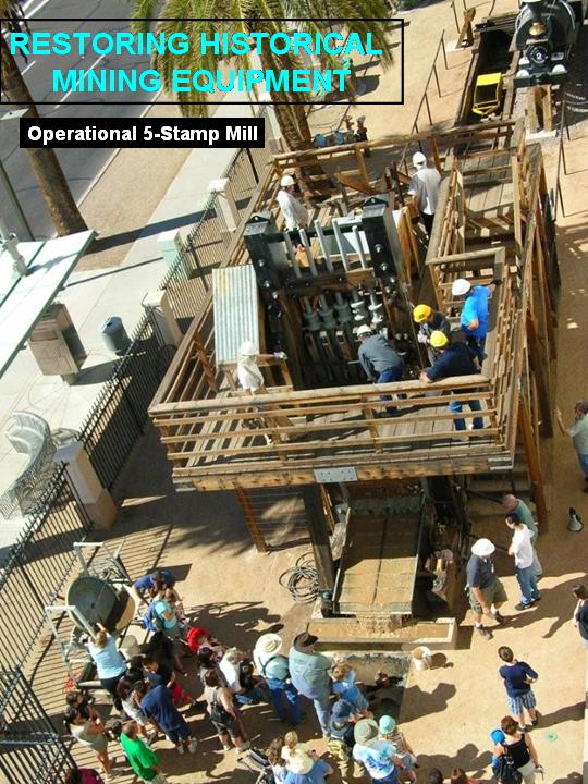
(4) Swallow Mine 5-Stamp Restoration Project


History of the Swallow Mine Stamp Mill: This stamp mill was used to crush gold bearing ores and deposit the fine gold on mercury coated copper plates. It is 19 feet tall, and the large drive wheel is 7 feet in diameter. The mill was operated by a 50 horse Western States single cylinder engine. The large metal structure at the base is called the mortar box, which contains the ore while it is being crushed. Water is used to move the materials out of the mortar box to a copper plate coated with mercury to absorb the gold as it leaves the mill. Each vertical rod (stamp) weighs 850 pounds and the stamp drops 120 times per minute from a height of 4 to 6 inches. The stamp mill operation crushes about 8 tons of ore in a 24 hour period.
This 10-stamp mill was originally installed during the 1890's at a small town called Briggs near Castle Creek, approximately three miles from the Swallow Mine. In the beginning the ore was transferred from the Swallow Mine to the mill, but after a few years the mill was disassembled and taken directly to the Mine where only 5 of the stamps were used. There are only two years of documented operation of the stamp mill during its service at the Swallow Mine. The first 1000 tons of material through the mill ran about $60.00 of gold per ton, or about 2 oz. gold per ton.
The picture below was taken in 1986 shows the stamp mill at the Swallow Mine before it was brought back to Phoenix. The mill was already partially disassembled when it was donated to the museum.

Millsite at Swallow Mine


Disassembly, Transport and Reassembly: This was the first stamp mill and second major project that I was involved with at the Arizona Mining & Mineral Museum. The stamp mill was donated to the Arizona Mining & Mineral Museum by the owner of the Swallow Mine, Charles C. Brown of Sun City.
The restoration process took from April 1996 to March 2003. This included disassembly of the mill, transporting the components from the mine 17 miles north of Wickenburg, AZ to downtown Phoenix, and assembly of the mill with all of the utilities. The job was completed with the help from Arizona Public Service Hauling Services and the Monday Crew, a group of about 10 to 12 volunteers that completed most of the work. This restoration process included sandblasting and painting all of the metal surfaces. Instead of using the gasoline engine a 15 Hp electric motor was used. A jackshaft was also incorporated to reduce the speed down to 60 RPM at the bull wheel. The original timbers were used after a cosmetic restoration was completed on the timbers surfaces.
This mill could be considered a “production mill”, since it has all of the attributes of an operational mill. This includes a rotational speed of 60 RPM, a 4” to 6” stamp drop, an operable automatic Hendy feeder, sluice tables with riffles and miners moss and fed with “gold bearing ore”.   I have found very few mills in the United States that could be considered production mills.
Installation at Downtown Phoenix


(3) How to Disassemble Rusty Mining Artifacts

Removal of nuts & fasteners from equipment: This is a very frustrating task and many times you want to save the specialized bolting materials. I have found that the use of chemicals (Kroil) and heat (torch) have the best results. Just using torque to remove the nuts from the component will generally destroy the nut/component. I have found the use of Kroil, a chemical that actually reduces the rust down to allow the nuts to be removed works well. Many of the old mining artifacts use National Fine threads and the chemical may not work. If you heat the nuts up to “red hot” you will almost always successfully remove the nut without damage.
NOTE: Kroil can only be ordered from the manufacturer; it cannot be purchased in stores.
Kano Laboratories Inc.

1000 E. Thompson Lane
Nashville. TENN 37211-2627
615-833-4101

Removal of cast iron pulleys from shafts: Cast pulleys are very susceptible to breakage if you try to use a steel hammer to remove them. You need to resist the temptation to use that method. In most cases there will be a key in a keyway. You should try to drive the key out using a hammer with a piece of stock as a push device. To remove the pulley you should use heat on the hub to swell the steel hub and then slide the shaft out using a soft metal mallet, applying it to the hub and not the outer rim. If this does not work, do not force it. If the shaft/ pulley are portable you could go to a machine shop that has a hydraulic press and have an expert remove the pulley from the shaft.

Removal of tappets from stamp shafts: You may want to move or remove the tappets from the stamp shaft. This is a common move to make the shoes all the same height from the dies.
NOTE: Only move the tappets on the stamp shaft if it is absolutely necessary. I have known groups that have moved the tappets and could not get them to stay in place. It seems the old miners had a better ability to fix the tappets in place.
If you have to move or remove a tappet from a stamp shaft you need to be careful that you do not break the tappet since they are made from a cast metal and could break with too much shock from a hammer.  You should use a good size torch with a rosebud to heat the entire tappet. The heat will expand the tappet for removal. Once you heat it to red, you can use a soft metal hammer and hit the tappet near the fat part of the tappet. This will shake the rust loose and you will actually see the rust come out between the tappet and the shaft. You should try to move the shaft after you have removed enough rust to move the tappet. The original fit of the tappet to the shaft is loose and once the years of rust have been removed the tappet should move freely on the shaft. At that time you can move or remove the tappet.  

If you have any comments on better or different ways to disassemble equipment, please respond in the comments section below.


(2) Mining Artifact Wood Preservation

Many of the artifacts are made of wood and are kept outside in the elements. If you do not treat the wood you will have rot, checking, weathering and overall deterioration. To prevent this you can apply the following preventive solutions for the artifacts that are in the elements. This has worked well in some projects that I have been involved with such as bull wheels and stamp mill parts.

Aging New Wood: If you have new lumber and want to age it and also preserve it you can use a chemical called Life Time Wood Treatment. This chemical can be applied with brushes or spraying the solution and will turn the wood’s color to an aged shade when placed in the sun for a day or so. The solution will also preserve the wood. It is not sold in stores. The following information will help you acquire the chemical:
Life Time Wood Treatment
Schroeder Log Home
www.loghelp.com
800-359-6614

Wood Hardener: Once the wood has been aged or is already aged you can apply the Clear Penetrating Epoxy Sealer. This chemical is applied with brushes or spraying the solution and will give the wood a rock hard surface. This will protect your wood from rot, dry out and checking. It is not sold in stores. The following information will help you acquire the chemical:
Clear Penetrating Epoxy Sealer
Smith & Co
www.smithandcompany.org
800-234-0330

Friday, July 13, 2012

(1) How I got started Restoring Mining Artifacts

How I got started Restoring Mining Artifacts


I started volunteering at the Arizona Mining & Mineral Museum in 1992 working on various projects.


History of the Boras: The Boras Headframe was the last of the wooden headframes built in the Warren Mining District near Bisbee, Arizona. Erected in 1917, it hoisted over 50,000 tons of copper ores by 1926 when the mine was closed during the Depression. Production resumed in 1938 and continued to 1941. In 1952 the headframe was reconditioned and some of its wood supports were replaced with steel. Until 1975 it served as a ventilation and escape shaft for the interconnecting underground workings of the Dallas and Cole mines. The relocation and reassembly to Phoenix was completed in 1997. The shaft served by the Boras headframe was 1,034 feet deep. The hoist motor was manufactured by General Electric and rated at 521 horsepower at 550 rpm. Maximum Speed of the hoist was 1,200 feet per minute. The picture below show the headframe and hoist in Bisbee
:

                                                       Boras Mine at Bisbee, AZ                    


Boras Headframe Project: My first major project started in 1993 and involved bringing a mining headframe and hoist house from the Boras Mine in Bisbee, Arizona to Phoenix. The headframe and hoist house were placed on loan from Phelps Dodge Mining Corporation, now Freeport McMoRan Copper and Gold Corporation. I worked with the Curator, Glenn Miller, and the Director, Mason Coggin, to put together a plan to disassemble, transport and reassemble the two major artifacts. The project took from December 1993 to May 1997. This was an education in how to take apart large components and move them. The main frame of the 35 foot headframe was transported in one piece and the hoist, weighing 17,800 pounds was lifted onto a flatbed and transported to Phoenix. This gave me an appreciation for the complexities of coordinating, disassembling, transport and reassembly of delicate mining artifacts. The picture below show the headframe and hoist in Phoenix:

                                          Boras Headframe at Phoenix, AZ