Sunday, August 25, 2013

(19) Underground Mining Equipment & Processes


The following is a study of underground mining equipment & processes. It includes the types of drivers used to transport the miners and materials underground, the devices that miners and materials moved through the mine complexes and the digging tools used underground.

Mine Engines
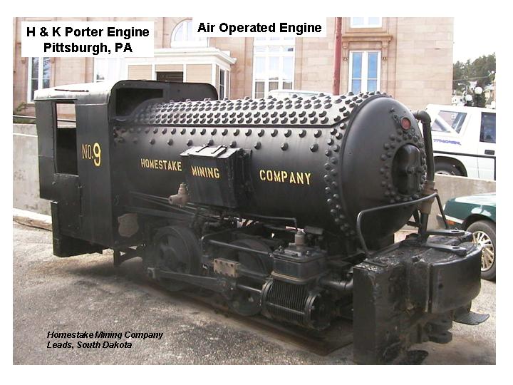
There have been several types of energy used to move miners and ore underground. They range from mules moving the miners and ore to air operated and electric conveyances.
The following pictures show some of the various types of engines that have been used over the years.

Note: Click on Images to make them larger


Personnel Transports
There have been several types of miner transports over the years for both vertical and horizontal transport.


Materials Transport
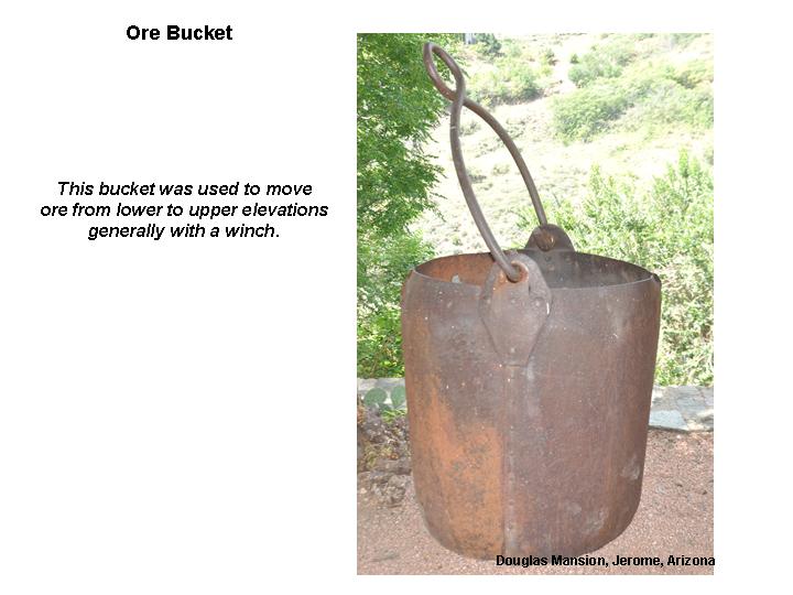
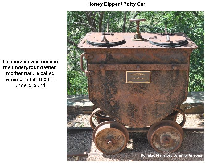
There were several different needs for devices to transport materials in and out of the mines including, ore, wood, steel, rock waste (muck), and also to remove human wastes from the mines.


Digging Machines
Miners have been inventive over the years starting with a pick and shovel and developing tools with mechanical advantage powered by steam, air and electric in their underground operations.


Saturday, August 3, 2013

(18) 1912 Publication on Stamp Milling

Stamp Milling A Treatise on Practical Stamp Milling and Stamp Mill Construction by Algernon Del Mar

This book contains a tremendous amount of information that is easily understood by most individuals that are interested in stamp mills and their processes. There are about 140 pages in this book and can actually be read like a novel. I know one individual that read through this book from front to back twice!

There is a brief history of the stamp mill starting in 1340, when they were used in the production of gun powder, and continues through 1900 which at that time stamp mills were considered quite modern. A nice thing about the book is that it has several illustrations that show early stamp mill configurations. In addition, it contains a wonderful history of the stamp mill.

The book gives an excellent accounting of the general principles of the stamp mill and discusses stamping, battery feeding, crushing capacity, power requirements and the cost of stamp milling.

It informs readers about problems that might occur during operations including broken camshafts, loose shoes and bosses, and how to prevent these accidents from happening.

There is an entire chapter on amalgamation. A discussion on amalgamation in excellent detail follows and points out practical applications of the process.

One of the most interesting chapters discusses construction and has many pictures and drawings to help understand how mills were assembled.

I recommend this book for anyone who is interested in learning more about stamp mills and how they work.  This book can be downloaded from the Internet through the following site: http://www.jeffersonminingdistrict.com/mining/Stamp_milling_1912.pdf    

Saturday, May 18, 2013

(17) What are Stamp MIll "Shoes"

Stamp mill shoes are the consumable attachment “shoes” on the lower end of the stamp shafts that crush the ore down to the consistency of sand. The stamp is made up of the stem, tappet, boss and the shoe which is attached to the end of the stamp stem. The drawing below shows the location of each of the components of the stamp. You can see the holes in the boss that allow removal of the shoe and the stem from the boss. The unusual thing is that all of the components associated with the stamp are press fit together, not screwed or threaded. The shoes are attached to the boss with hard wood shims. Shoes are frequently replaced since they do wear down by crushing the ore that is sometimes quartz which is very hard. The shoes start out about 6” to 9” of steel pad that will wear with use. The rule of thumb is if the shoe pad gets down to less than 2” thick then it needs to be replaced.  The shoe is removed by placing a drift pin in the lower hole of the boss and forcing the cone on the shoe out of the boss. Once the new shoe is placed in the mortar box, the stamp is dropped on to the shimmed cone of the shoe and presses itself to the stamp.
 
During a previous stamp mill restoration, we got to the stage when we needed to install shoes for a 10-stamp mill project, but there were no shoes with the artifacts for the mill. The shoes were classically made from steel castings, so I tried to find a foundry and there were no foundries in Arizona that would cast the shoes. I went to three other foundries out of state and was surprised with the cost of casting shoes. I contacted the Star Foundry and Machine Company in Salt Lake City, Utah; Kit’s Foundry & Machine Inc. in Shelley, Idaho and  AFFCO in Anaconda, Montana and their quotes for the shoes was more than the museum had figured into their budget. Part of the cost is that you have to pay for the manufacture of the casting that the shoes will be poured into. That ran from $125 to $350 for the casting. The cost of the metal ran around $3500 for 10 Stamps. This was for shoes that included some manganese “hardener” in the castings.
The decision was made to make the shoes from 9 ½” bar stock. We found a supplier that had some used hydraulic piston shafting that had manganese hardener and we got the material for $600 for the 10’ of 9 ½” shafting. The more expensive part of the process was the machining of the cone on the shoe. That came to about $2,000. We saved over $1,000 plus we had some very hard shoes and did not have to pay for shipping.

I found a bill of sale for steel shoes (below) for a stamp mill back in 1912. Joshua Hendy was an important producer of stamp mills back in the late 1800’s. The cost back then seemed to be inexpensive at $21.00. I did a study on mining prices in 1915 as compared to 2012 and found that back then the stamps were actually more expensive in comparison to today’s prices. The quote I received on the cost of the shoes would have come to $3,850. The Consumer Price Index (CPI) for 1915 is equal to $1 = $23 in 2012 using the formula on the Website  
http://www.bls.gov/data/inflation_calculator.htm. The 1915 cost with the CPI came to $4,830 in today’s money. That was $1,000 in today’s money more for the 1915 prices.
 

Sunday, April 21, 2013

(16) 1915 Mine Productivity Determination

I conducted an historical review on a small local Gold Mine and during the research I found an actual evaluation of the production of the mine completed in April 1915 by a local geologist. I have developed two slides that show the production values of the mine.

The first table below discussed the Mine Assay Values. Four samples were taken from various locations in the mine and assayed for gold and copper, the prevalent ores in the mine. Each sample was analyzed and they came up with a dollar value per ton. Today we use ounces of the ore instead of dollar value since metal prices fluctuate quite a bit. As noted on the table the 1915 gold and copper values were $21 per ounce for gold and $0.08 a pound for copper. I made up a second column for the gold and copper prices in 2012 with gold being at about $1,700 per ounce and copper being approximately $3.55 per pound. You can see that the average per ton was $27 and at today’s prices it would be $1,500 per ton. The results were that the mine had some good ore values.
He went on to determine if the mine operation could continue on the ore values that were found. This is where the second table below for Mine Production was used. This takes into consideration all of the individual operating costs. It is interesting to see how much each component would cost in 1915. To find out what the comparable prices would be today I used the Consumer Price Index (CPI) for today as compared to 1915. The factor was $1 in 1915 which would be worth $23 today. I developed a second column and used the price of each item times 23 to get the cost today.  The engineer totaled each of the individual cost of mine operations. Once he had those figures the mining mechanism, a 10-stamp mill, was factored in to determine how much ore could be processed. It was determined that the mill could process 30 tons per day. The profit was determined by subtracting the mine operating cost per ton from the mine production per ton and multiplying that number by 30. The geologist determined that the values obtained were adequate for the mine to stay in business. The actual operating cost today will be more, in that, there are other costs that are included such as reclamation costs that were not in place in 1915 and would make the final cost of operations much more and the total profit less.  
       

(15) American Boy 10-Stamp Mill Progress

I have been involved with the restoration of this 10-stamp Mill at the Mojave Desert Heritage & Cultural Association in Goffs, California. The restoration was started about three years ago and is proceeding well.

We last worked on the American Boy stamp mill on the weekend of April 11 through April 14:  There were (9) volunteers that participated in the significant progress made that weekend. The following work was completed:

Transition Deck Installation The purpose of the transition deck is to allow operators to access the upper ore bin deck from the back of the mill and walk around to the operator’s deck. This keeps the front of the stamp mill visible and eliminates the need for a pair of stairs in front of the mill. The picture below shows the transition deck being installed: 
Railing and Kick Plate Installation Railing had to be installed to keep the operators from falling off the deck and keeping them clear of the rotating equipment. The 6” kick plates along the base of the walkway keep tools and other items from falling on personnel under the deck. 
Installation of the Staircase The staircase was donated by the Superstition Mountain Museum, Apache Junction, Arizona. The staircase had to be modified to overlap the deck and assure that the staircase would be securely anchored to the upper deck. There was also a platform constructed to set the bottom of the staircase. The platform is not shown in this picture. 
Finished Transition Deck and Access Staircase The deck assembly went off with great success. The deck allows access to the operator’s section and protects the operators. 

Jackshaft Stiffener Installation The jackshaft moved slightly when running the mill, so railroad ties were used with concrete anchors to stiffen the jackshaft. The modification was a great success making the jackshaft “rock steady” during mill operation.  
Detroit Diesel engine The engine pulley was changed to a smaller pulley to allow the engine to run at its optimum speed (approximately 2000 RPM) and have the speed of the bull wheel at about 60 RPM. When the engine was run it sounded much better and will significantly improve the life of the engine. The engine was moved further away from the deck to allow better utilization of the engine adjustment. The engine was run twice and the bull wheels engaged. The belts tracked well and the overall operation is ready to start dropping shoes after the idler pulleys are installed. 
A presentation was made after the Saturday Evening Dinner. FedEx Express in Irvine, California donated drive belts for the American Boy Stamp mill. They also donated belts to two other museums. The picture below shows the collage of pictures of the Goffs American Boy 10-stamp mill, Cave Creek’s Golden Reef 10-stamp mill and Superstition Mountain Museum’s Cossak 20-Stamp Mill. In the picture from left to right we have Roger Camplin representing Superstition Mountain Museum, Nance Fite representing FedEx, and the recipient of the collage, Hugh Brown the Executive Director of the Mojave Desert Heritage & Cultural Association and finally Charlie Connell (author of stampmillman) representing Cave Creek Museum. 

The following are some additional pictures of the status of the mill in late April 2013. We are expecting the mill to be operational by September 2013.


Monday, January 14, 2013

(14) Upcoming Mining Artifact Shows & Events

UPCOMING MINING ARTIFACT SHOWS & EVENTS
2014 (UPDATE 6/2014)

I have listed a grouping of specialized mining artifact shows that are selling nothing but mining artifacts. There are not many of these shows in the US, but I have been to the one in Tucson, Arizona and one in Grass Valley, California. Both shows had some extremely nice items, both small and large such as small blasting cap boxes to ore carts and other large components. There have actually been entire stamp mills for sale at these shows. If you have never been to this type of show, I think you will find it interesting if you like old mining artifacts.
There is currently only one show in the Nevada City area that is rich in mining history and while you are there you should visit the North Star Mining Museum in Grass Valley and also the Kentucky Mine tour in Sierra City, California. They both have stamp mills that are in excellent shape.  


2013 Mining Antique Collectors Swap Meet and Auction
Date:                Saturday, June 28, 2014
Location:          Nevada City Elks Bldg, 518 Highway 49, Nevada City, CA
Swap Meet:      9 AM – 4 PM, open to the public at 10 AM, Set up 8 AM
Social:              4:30 – 6 No host bar at Elks
Dinner: 6 PM  $30 per person
Auction:            Immediately following the dinner
Further information?  dwkfargo@aol.com


Wednesday, December 5, 2012

(13) Constructing A Mining Ore Skip Cart

Constructing A Mining Ore Skip Cart

Mining ore cart skips were used on shafts that were incline. The incline could be anywhere from a 30 degree angle to greater than an 80 degree angle. The skips were constructed differently than the regular back dump and side dump carts that you are use to seeing. They were open on one end and could have the top partially covered. They would bring the ore up to the surface and then dump the material in an ore bin. The picture below shows an incline shaft cart in operation.


There are many different sizes and shapes of incline skips, but they all have a front end open with some coverage on the top of the cart.

I designed an incline skip to be used with certain size restrictions and the drawing below shows the basic size of the sheet steel parts for the construction of the box.


The drawing below shows the construction of the skip, including the overall dimensions for the skip.
The side view of the skip shows the bail. This device is tied to the back of the winch and controls movement of the cart. It is made from approximately 16 feet of 2" X 1/4" strap steel listed on the additional parts list. The 3 views of the completed skip towards the end of the lesson gives you a better perspective of the additional minor materials to construct the cart. You need to find (4) approximately 8" wheels and (2) 16" axels to fit the wheels to complete the parts for the skip.  

The pieces of the skip were made from 1/8” steel plate. There were over 100 cold rivets used to assemble the skip with no welding involved. This is patterned after skips made in the 1800’s. The more recent skips do not use rivets and are welded together.

I have some pictures of the skip during construction below that show how the skip was assembled. You have to be careful assembling the skip so that you can hammer the rivets without problems with clearance. You will need about 15' of 1 1/2" light wall angle iron to assemble the skip.  The first step was to install the angle iron and rivets on the back side of the box as shown below:


You will need about 6' of 1 1/2" flat steel to complete the front sides of the cart. The next step was to install the sides of the skip:


Once the side was riveted together I installed the bottom plate and installed the rivets on the final side of the box.


The picture below shows three views of the skip box completed. I had to install the small top cover and it was assembled with carriage bolts so that the top could be removed for maintenance. The last steel to be placed on the box was the bail. This allows you to pull the skip up from the mine and gives you flexibility to dump the skip.
Once the skip box assembly was completed we installed the wheels and axels on the bottom of the skip. The picture shows the assembled skip on an incline. The incline is still being constructed in this picture as well as the placing of the crusher over the skip.