
GOLDEN REEF MINE
TRAMWAY
New Tram Tower Construction
Chapter 3 of 5
This is
the third part of the Golden Reef Mine Tramway project. The second chapter gave
us the design of the tramway.
NEW TOWER CONSTRUCTION
Since
we could not remove any of the towers from Continental Mountain we decided to
build our own towers. The first thing we had to do was to go to the towers and
take detailed measurements so we can determine what it will take to build two
towers.
Tower Measurements We made several trips to the towers still
standing to take measurements. The two pictures below show each piece of wood
and its dimensions:

Tower Materials Specifications The table below shows the original tower
timber dimensions on the tram towers. The numbers in the parenthesis are the
dimensions of the timbers used on the towers. he larger timbers add to the
design and strength of the towers.

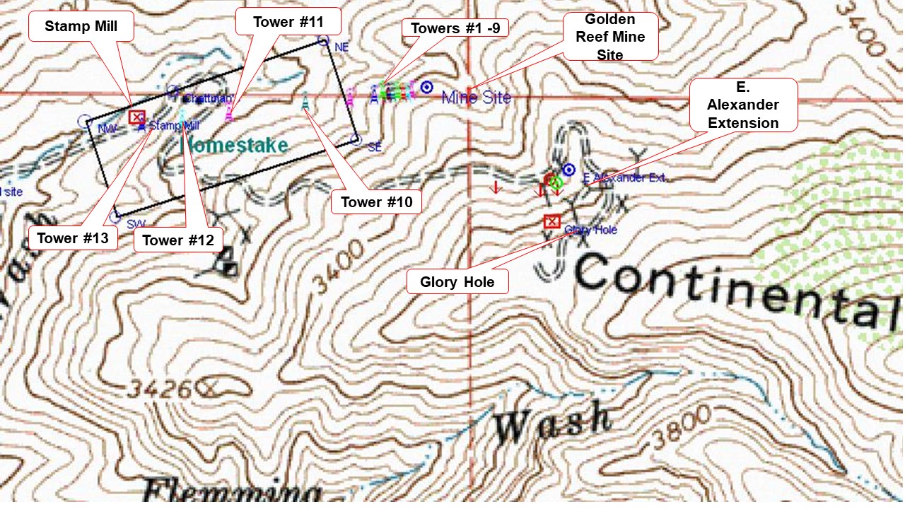
Golden Reef Tramway Visits We made a number of trips to the lower part of
the tramway on the Chatman’s Homestake Patent. We needed to find the metal
tower supports and the moving cable guides. The wheels for the moveable guides
were found at the original location of the stamp mill and I purchased another one
at the Tucson mining artifacts show. There are (4) tower locations on the
Chatman’s patent, Towers #10, #11, #12, and #13 that had fallen down, but still
had some metal artifacts on them. See the topo with GPS coordinates (colored
towers) superimposed below:
Tram Tower Metal Parts We spent some time going over the (4)
tram towers on the Homestake Patent after getting permission to obtain metal
parts and cables on the (4) towers from Joni Chatman, the owner of the
Homestake and the stamp mill. She donated the stamp mill to the Museum several
years ago. The group spent many hours searching the fallen down tram towers on
the Homestake Patent. We found everything we needed except for one of the metal
struts for one of the towers. The following parts were retrieved from the
towers on the Homestake:
Tram Tower #10 This tower is in bad shape with most of the hardware missing. There were
(2) of the struts and strut supports, 1/18” & 7/8” cables running through
the tower remaining.

Tram Tower #11 This tower had (2) sets of the 7/8”
moving cable guide bases, (1) 1 1/8” stationary cable guide and support, 1 1/8”
& 7/8” cables, and (2) rod struts.

Tram Tower #12 The wood in this
tower is in bad shape and there are (2) base plates & plate guides and 1
1/8” & 7/8” cable running through the area.

Tram Tower #13 This tower was very
close to the stamp mill and what was the lower station. The only things left
are the foundations and 1 1/8” & 7/8” cables running through the area.
Lumber Purchase After we got all of the measurements we
went out to purchase the wood. We purchased rough cut fir and many of the
dimensions exceeded the dimensions of the original wood. The picture below
shows the pile of wood to construct the (2) tramway towers. We marked each of
the timbers with their designated use:

Interlocking Timbers The next task was to assemble the two
towers. Most of the pieces were cut and notched and interlocked to give them
added strength since they were going to support cables that would have over
4,000 pounds of tension (weight) on them during operations. The pictures below
show the use of notches in the construction of the towers:

Test Cuts Made on Certain Tower Pieces The two pictures below show another example of
the craftsman ship required to fabricate a quality tower. The metal guide in
the picture sits on the cross members on top of the tower that will hold the 1
1/8" cable that could hold over 4,000 of tension when the towers are in
operation. The piece of test wood was used to make sure that the cuts are
accurate and tight fitting when cut for the actual pieces on the tower.

Tower Assembly We built part of the tower on the ground to make it easier to put it
together. Once the tower “half” was assembled on the ground it was then up
righted and the rest of the tower assembled. The picture below shows the up
righting of the tower.

Backstay Installation Once the tower was up righted we had to
manually install the other major components. This was a teamwork effort as seen
below.

Tower Assembled We finished the wooden part assembly of
the tower with it standing upright. We moved this tower aside and constructed
the second tower. It was very handy to construct the towers under this shade.
It kept the sun and rain off us during construction.

Tower Construction Complete We added the steel parts of the towers
including the upper tower braces and the moving cable pulleys that keep the
moving 7/8” continuous cable off the ground when the tram bucket is not by the
towers. We also put wood preservative on the tower to keep the wood safe from
the Arizona sun.

Tower Transport We put the towers on a trailer and then moved them to the museum to
their final resting place.

This completes the construction of the
tram towers. The next section will go over the installation of the towers on
site at the museum.
NEXT: Chapter #4 Tram
Tower Installation
No comments:
Post a Comment