
This is the fifth and
final chapter of the Golden Reef Mine Tramway project. The last chapter covered
the assembly the towers.
TRAM
TOWER STATIONARY CABLES
Critical Alignment
Checks We shot the
alignment of the 1 1/8” cable guides that will hold the stationary cables in
place. The tram buckets will be suspended on those cables and if the alignment
was off the cables could dislodge from the guides and bad things happen. The alignment was perfect and we will have no
trouble with the guide alignment. The picture below shows the location of the
guides.

Tower
Anchor Components The
design section identified the swages, turnbuckles and shackles needed to anchor
that two 1 1/8” stationary cables. The needed components were purchased and
next step was to assemble the components.
Measuring
Cable Lengths We took
the cables and stretched them across the tower cable guides to mark the cables
with the swages, turnbuckles and shackles installed. We used cable clamps to
stretch the cables so they could be marked where the vendor needed to cut and
install the swages. The picture below shows the temporary clamps to stretch the
cables.

Transporting
Cables to Vendor We
removed the cables from the towers and put them into a trailer to transport
them to the vendor that will install the swages. You are probably wondering how
we moved the 70-foot cables from the museum to the machine shop and back. The
picture below shows how we moved the long cables.

1
1/8” wire Rope Connectors
We cut the two 1 1/8” cables to allow for the length of the connectors and then
took the two approximately 70’ cables to a machine shop and had the swages
pressed on to the cables with a 30-ton (60,000 pound) press. The picture below
shows the machine used to press the wire ropes on the swages.

Transport
of Wire Ropes We
brought the cables back to the museum and installed them on the tram towers
with a trailer. The picture below shows the cables with swages installed ready
to take back to the museum and installed on the towers.

Installing the Cables We used manpower to loop the cables
over the towers and then tightened them down with the cable clamps that Pete
supplied.

Cables
installed The cables
were installed and the turnbuckles were adjusted. We did a load test on the
cables and they passed. The test was performed with buckets filled with water
to a weight of about 350 pounds and then the cable droop was measured and it
was within the 18” droop requirement. See
the setup below:

After
the cables were installed, we laid out the location of the continuous cable
horizontal pulley was placed where it would be when the driver and driven
structures were installed.

TRAM
BUCKETS
Tram
Buckets We already had
the original tram bucket and hanger and they were installed. It took a little
longer to obtain the other bucket and hanger. We took the original bucket over
to Cave Creek Welding and they offered to construct an identical bucket to fit
on the hanger we got from California.

TRAM
BUCKET INSTALLATION
Tram
Bucket Installation Now
that we have the stationary cable installed, we need to install the tram
buckets. There was much discussion about how to do the activity and as usual
everyone had an opinion. We ended up with two plans and both of them are
displayed below. You make the decision which one is safer.
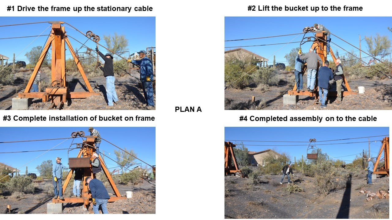

The
picture below shows the installed tram buckets ready to install the moving
cable.

DRIVER
& DRIVEN MECHANISMS
Driver
& Driven Foundations and structures These components are critical to the operation of the
tramway. These components will actually allow the tram buckets to travel back
and forth on the 1 1/8” stationary cables. The moving 7/8” cable will not have
very much tension, just enough to keep the slack on the drive motor roller. This
part of the project was to excavate, construct driver driven frames with rebar
and then pour the concrete.
The
pictures below show the stages of the completion of the Drive end
installation.

The
pictures below show the stages of the completion of the Driven end
installation. The final assembly consisted of installing the sliding tower
attached to the backstay with (4) 1” all thread to allow sliding adjustment to
obtain the desired tension on the traveling cable.This is the component that will adjust the tension on teh traveling cable.

Traveling
Cable Installation This
process required two activities. First we had to install the two 38” horizontal
pulleys on the driver and driven ends. We had to weld a shaft spacer on the top
end of the 2 5/8” shafts to accommodate the pulleys. The picture below shows
the spacer being welded on the driven end station.

Teamwork
enabled the pulley to be installed on the vertical shaft. The cable will then
be stretched over the horizontal pulley.

The
traveling cable had to be lifted with linemen pulleys on the stationary cable and then pulled up with a
com-a-long to the desired tension.

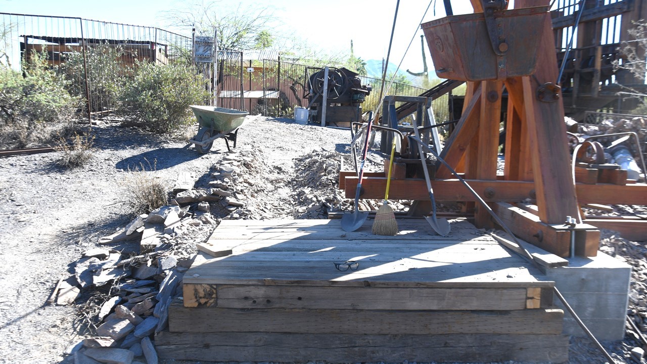
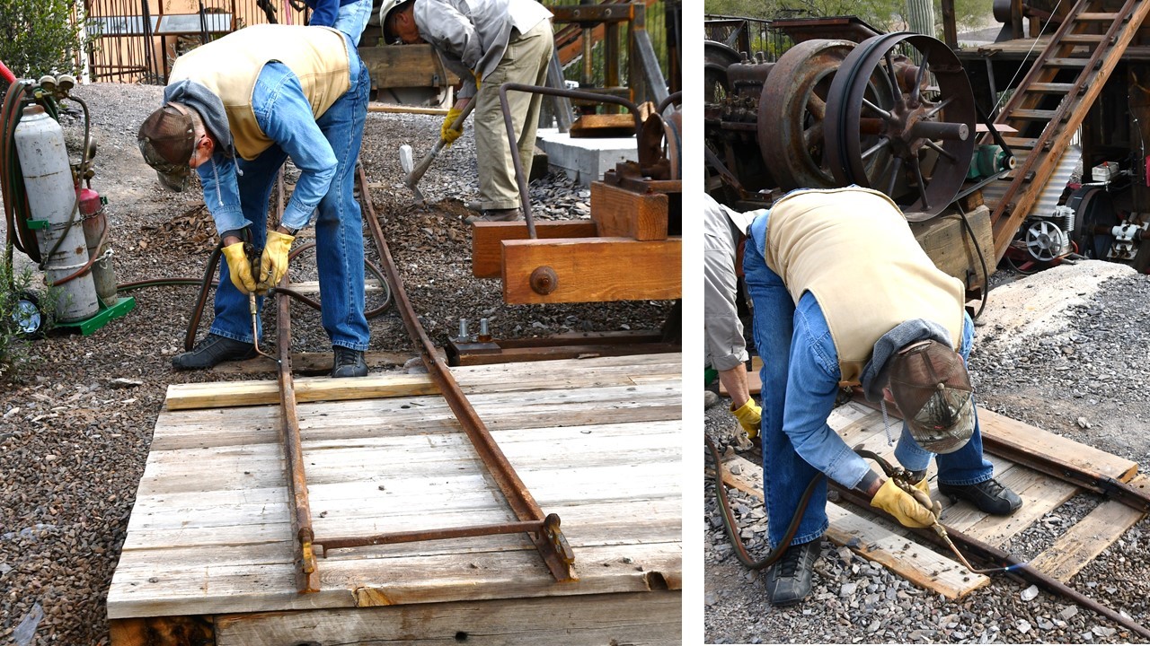
TRAMWAY
TO STAMP MILL TRACK
We installed rails from
the tramway bucket station to the stamp mill crusher. This is how the materials
got form the tramway to the primary crusher on the stamp mill. The pictures below
show to construction of the track and platforms.


DRIVE
MOTOR INSTALLATION
Drive
Motor Design This is a
special motor for this application. It is low speed, 67 RPM and has lots of
torque to drive the tram system. It is also a reversible motor so that we can
run the tram buckets back and forth on the stationary cables. The motor is
shown below.


We had
to weld the base plate onto the cross member to mount the motor in a position
that allows the roller to contact the horizontal pulley. We used (4) 3/8” bolts
to adequately anchor the motor. The plate was welded and ready to install the
motor.

The
picture below shows the motor installed and ready to be tested. We tested the
motor moving the tram buckets back and forth several times for all that were
observing the initial operation of the tramway. It takes the buckets about 30
seconds to make the 50-foot trip from one tower to the other tower. The
original tramway was 2,000 feet long. This is the only
Bleichert’s Double Rope Mining Tramway that operates in the USA, that I know of.
Bleichert’s Double Rope Mining Tramway that operates in the USA, that I know of.

THE END
No comments:
Post a Comment